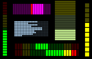
LedControls - a Lazarus Visual Component Library
Background
The LED as light-emitting semiconductors was invented in 1962. I have been invented a year before so I could follow the development from the beginning. In 1992 Shuji Nakamura invented a blue LED which was the base for the latest revolution of illumination. He got the Nobel prize. Around 2014 I decided to bring the LED-7-Segment modules to modern computer displays in web applications. They refused to reward me with a Nobel price, so I decided to bring LEDs to Lazarus.
Intro - 4 LED-style visual Controls
The following 4 components may be used to visualize any processes behaviour. Iam using the Led component in many Delphi applications to signal states like incomming data, saving processes or processing results (green for ok, yellow for critical, red for alert). The 7-segment-led display may be usefull to display numeric values of measurments. The LedMeter component displays single values tendencies graphically with their possible limits.
 |
TBlinker | Select an existing leds image with one of 7 colors or define a .png file with an image designed with Greenfish Icon Editor, Inkscape or whatever. Let your Led blink continuously or once. |
Intro Reference |
 |
TSegmentDisplay | Define 7-segment-led modules and assign them a text to display. There are many styles and design details you can configure to give them an individual look. |
Intro Reference |
 |
TLedMeter | A control with many styles to display single analogue values or vectors of values. |
Intro Reference |
 |
TSignalStrength | Displays a signals strength or whatever. |
Intro Reference |
Download
LEDControls is available on GitHub:
https://github.com/Atomek61/LEDControls
Installation
I developed and tested the components with Windows 10 but I dont see a reason not to use them under other graphical operating systems.
- Make sure you have installed the BGRABitmapPack. It is used by TSegmentDisplay.
- Create a folder in your Lazarus source directory like Atomek.Controls/
- Copy all the downloaded files to this directory
- Open the package with Package|Open Package File...|ledcontrols.lpk
- Install the package with Use|Install
 | TBlinker |
A Blinker lets an image toggle periodically between two images - a bright one and a dark one. So you need an ImageList control which contains pairs of images.
- Place the Blinker from palette Atomek on your form
- Place an ImageList (palette Common Controls) on your form
- Double-click the ImageList, Add.. the file LEDs.png from Atomek.Controls and split it
- Select the Blinker and set the ImageList property with the newly created ImageList
- Select the LED to be displayed with the properties ImageIndexOff and ImageIndexOn (0 and 1)
- Activate the Blinker with property Active := true
Key features of the Blinker component are the boolean
Active property
and the Mode
(bmContinuously or bmKeepAlive).
Find all details in the TBlinker reference.
 | TSegmentDisplay |
After placing the control on your form two steps are important:
- Define the
modules, exampleSegmentDisplay.Modules := '8.8.8.8.'; - Display a
textwich matches the defined modules, exampleSegmentDisplay.Text := '234.5';
The default modules definition is "8.8.8.8". This means there are 4 8-segment modules. An 8-segment module can display all 7 cipher segments and a dot. A matching text may be "-1.23". The modules are filled from right to left. Missing symbols are interprated as SPACE, missing modules are ignored.
Examples for module definitions:
| Clock, long form | '8888888888_88:88:88.888' |
| Text | '2018-05-03 07:23:45.678' |
| Clock, short form | '88:88' |
| Text | '12:34' or '12 34' |
There are really a lot of design features available to enable you to create an individual LED segment style. For details see the TSegmentDisplay reference.
Use one of the predefined color sets or use your own colors for bright segments, dark segments and for the background.
![COLORSET[1]](COLORSET1.png)
![COLORSET[2]](COLORSET2.png)
![COLORSET[3]](COLORSET3.png)
![COLORSET[4]](COLORSET4.png)
![COLORSET[5]](COLORSET5.png)
![COLORSET[6]](COLORSET6.png)
![COLORSET[7]](COLORSET7.png)
![COLORSET[8]](COLORSET8.png)
Available modules are
| "8" | 7-segment module |
| "8." | 8-segment module |
| ":" | Double dot (for clocks) |
| "_" | Spacer |
Displayable symbols are "0123456789AbCdEF-.:" and SPACE. You can define other symbols
in the OnDrawSegments-event.
 | TLedMeter |
This control displays one or more numerical values as colored bars made of discrete led elements.

Define the controls styles, define the colors and their ranges and set the levels to be displayed.
BarCountdefines the number of barsOrientationisloVerticalorloHorizontalStyleislsNormalorlsBiDirectionalLevels[]contains the bars levels as single precision valuesColorNodesis a collection containing color/level pairsSegmentSizedefines the height/width of the segments. 0 means quadratic.MinLeveldefines the minimum level (Mode=lsNormalonly)
Hint: many technical values (audio pressure) are displayed logarithmic (dB). Its a good idea
to assign Levels[i] := Log10(Value); instead of a linear scaling.
 | TSignalStrength |
This control displays a signal strength level. You can define the colors and the minimum and maximum levels.
BarCountdefines the number of barsLevelis the current levelMinLeveldefines the lower limitMaxLeveldefines the upper limitOnColordefines the bright segments colorOffColordefines the dark segments colorGapSizedefines the width of the slit between segments.
Hint: many technical values (audio pressure) are displayed logarithmic (dB). Its a good idea
to assign Level := Log10(Value); instead of a linear scaling. Dont forget to
enter meaningfull limits for this level.